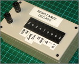
Project 005 - Resistance Decade Box
DISCLAIMER: This design is experimental, so if you decide to build one yourself then you are on your own, I can't be held responsible for any problems/issues/damage/injury that may occur if you decide to follow this build and make one yourself.
INTRO
 Any good electronics workshop will have a suite of test equipment, mostly purchased but some home made. This project falls into the latter category as I have built myself a Resistance Decade Box.
This isn't a military spec design but rather uses components from Ebay (as ever!) and in addition it's a small lower power build using cheap switches and resistors rated at only 1/6W. However, I have pushed the boat out in one respect giving the range of the box from 0.1 ohm all the way up to 99.9999999M ohms.
PARTS LIST
1 * ABS enclosure (150x75x50mm)
9 * Pushwheel Thumbwheels (KM1 0-9)
2 * 4mm chassis mount banana sockets
9 * 0.1 ohm, 1/6W resistors (1%)
9 * 1 ohm
9 * 10 ohm
9 * 100 ohm
9 * 1k ohm
9 * 10k ohm
9 * 100k ohm
9 * 1M ohm
9 * 10M ohm
TECHNICAL
Accuracy:
I elected to use 1% tolerance resistors in my design, so by my reckoning gives my box an overall accuracy of better than 1%. But with all those resistors how can that be?
Suppose we have 10off 100 ohm resistors in series thus making 1k ohm total, and suppose each of these resistors is at the lower limit of tolerance at 99 ohms. We will therefore have a nominal value of 1000 ohms and an actual value of 990 ohms. The deviation between actual and nominal will be 10/1000 = 1%. Worst case then, the accuracy of 10 resistors in series is no worse than one resistor.
However, and this is where I pick up on the "better than 1%" statement. If we suppose the individual resistors have a random deviation from the nominal value, then some negative and positive errors will cancel out when ten resistors are combined thus the likely error on the combination will be less than the error individually. Statistics at work.
Schematic diagram:
Note: 3off the 9 switches are shown.

PHOTOS (LATEST AT THE TOP)
12/11/11 - The Build.
The finished item.

Due to lack of switch end plate availability (typical cheap Ebay gear) I made the cut-out pretty tight for the switches, and used some metal backed tape to hold them in place. They aren't going anywhere.
Main components ready for final assembly:
All the resistors fitted to the switches and wired together:
The switches I chose have a handy row of holes perfect for mounting the resistors. The two remaining holes are used to connect to the adjacent switches.


